Broken since 3 July 2026 · 110 days

My laser broke. Please help me fix it!

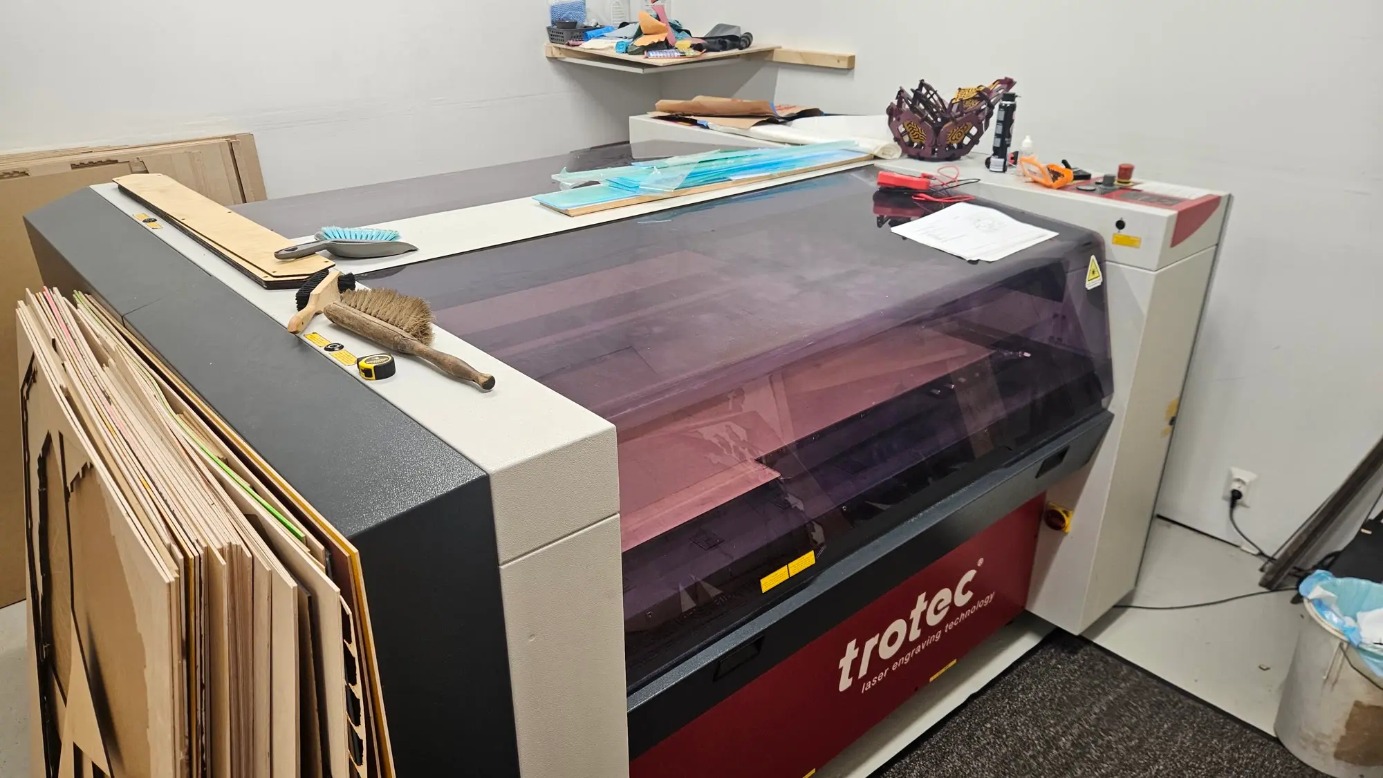
My 2008 Trotec TP1313 laser cutter died mid-cut and won’t start. Trotec stopped supporting it in 2017. If you know these machines, what should I check next?

When I switch it on

Should

Click, beep Head moves to zero Ready beep

Does

Click, 2 beeps Dark panel, no movement Beep?!

Should: relay click, a beep, the head moves to its zero position, then a ready beep. Does: relay click, two beeps, the control panel stays dark and nothing moves, then after a while a ready beep anyway.

Hello

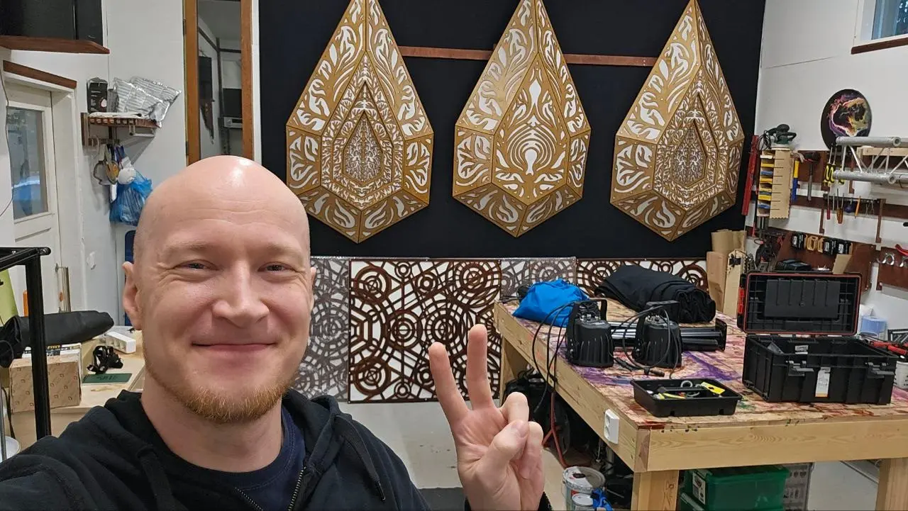
I’m Heikki, a Finnish artist working as Hexagon Intergalactic. I build installations, festival stages and interiors.

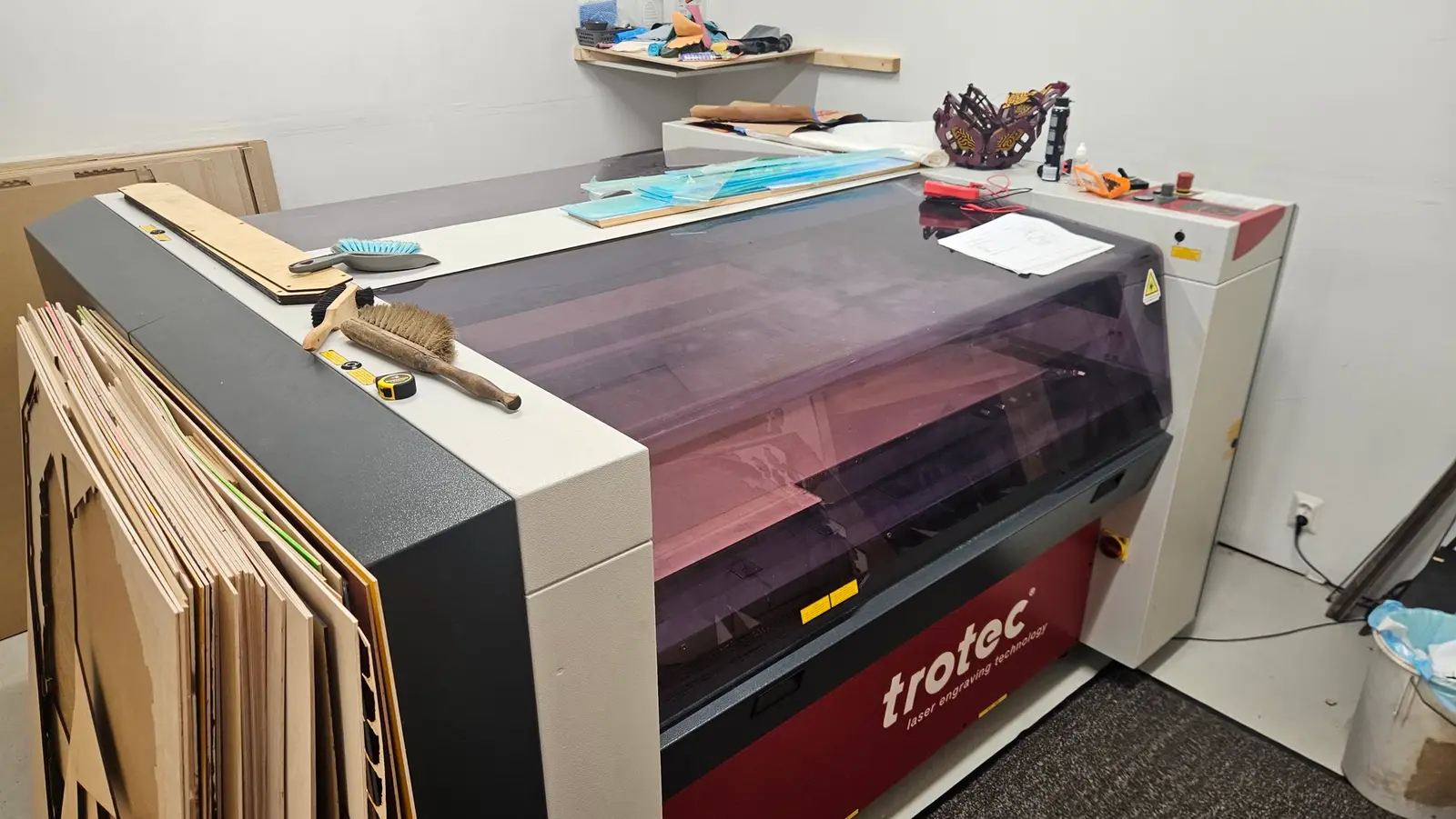
Heikki smiling and flashing a peace sign in his studio, with laser-cut wooden wall pieces behind him My Trotec TP1313 laser cutter with a smoked purple lid, in the studio with plywood sheets leaning against it

What happened

I was in the middle of a cut when the machine stopped in its tracks with a thunk, the same sound it makes when you switch it off. No laser, no movement, no lights on the control panel.

The last line in the error log is code −204, logged at 13:34 on 3 July 2026. Since then it powers up but never becomes ready.

It could be one cheap part that failed, but I don’t have the electronics experience to find it on my own.

Video transcript
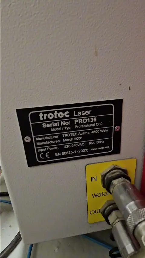
  1. Okay, so here’s the machine and the problem. Here’s the serial number, PRO136.
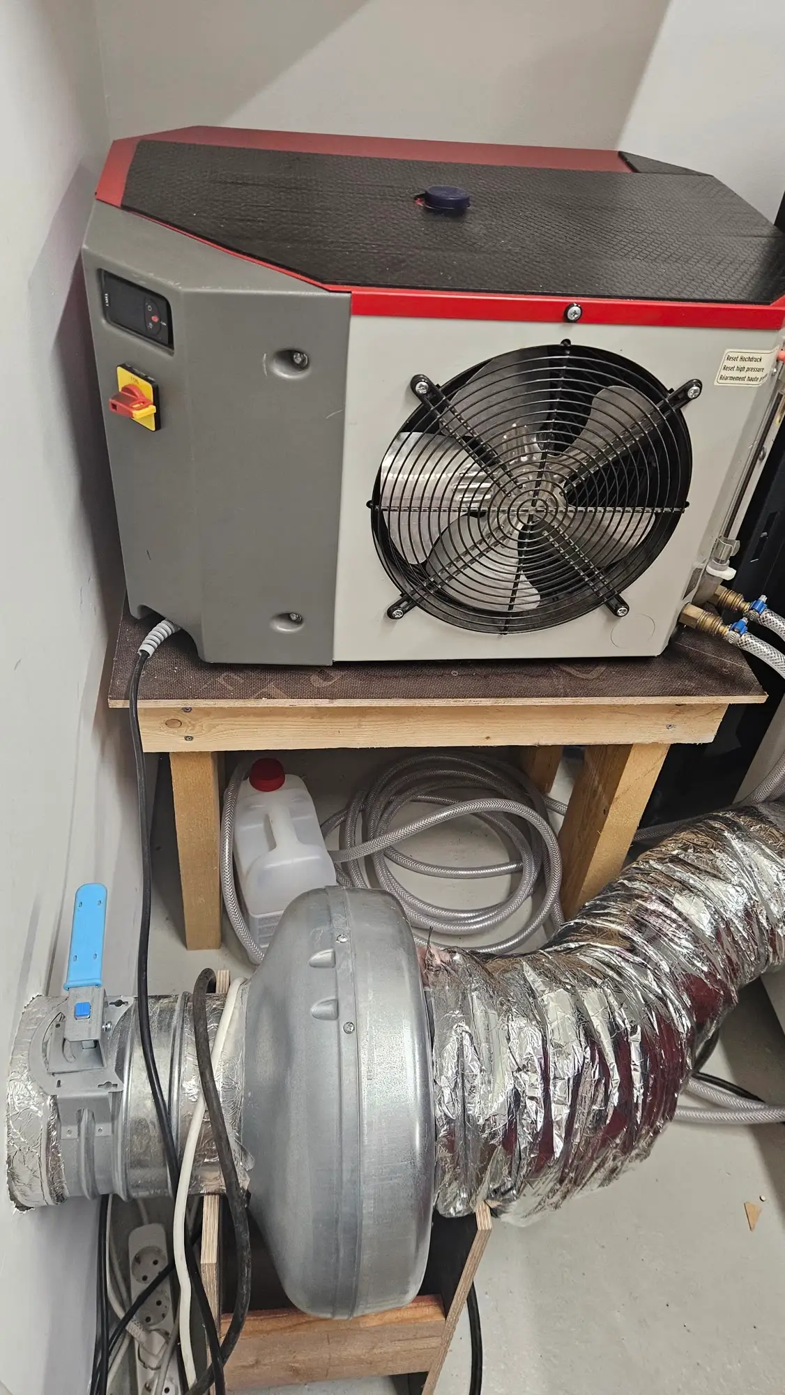
  2. So, I have a cooler. We can see that it is at 6 litres per minute, so the water is circulating.
  3. And now, here we can see the problem. When I turn it on, it should go plonk and beep and the lights should go on.
  4. Two short beeps, beep beep, and no lights go on.
  5. There was a third beep, which would sound like everything is fine, but nothing’s fine.
  6. The controls don’t work, the head doesn’t move, it does not seek the zero position in the beginning, and no lights appear at all.
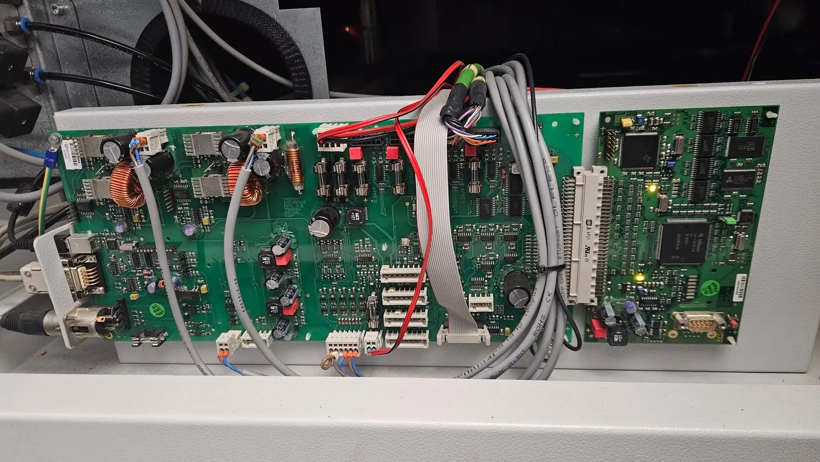
  7. [Inside the machine] I can see that the lights are on, at least these ones. I’ve checked all of the fuses.
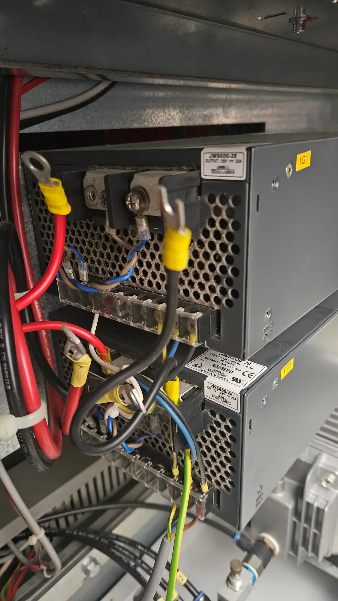
  8. Okay, and the power supplies. This one is 48 volts and measures at the output 48 volts. These ones… [on screen: “28 V supplies measure at 32 V?”]

Open on YouTube

What I’ve checked

Not working

  • Power-on sound Relay click and 2 short beeps (should be 1). A “ready” beep comes later anyway.
  • Cabin door Open and close the door: a few seconds later the long “ready” beep sounds, as if nothing were wrong. Panel still dark, head still parked.
  • Control panel LEDs None light up
  • Homing (seek zero position) Laser head doesn’t move at all
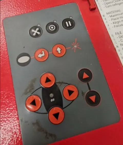
  • Keypad on top of the machine No response, no lights. Should blink green.
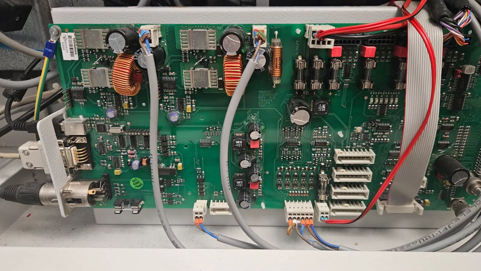
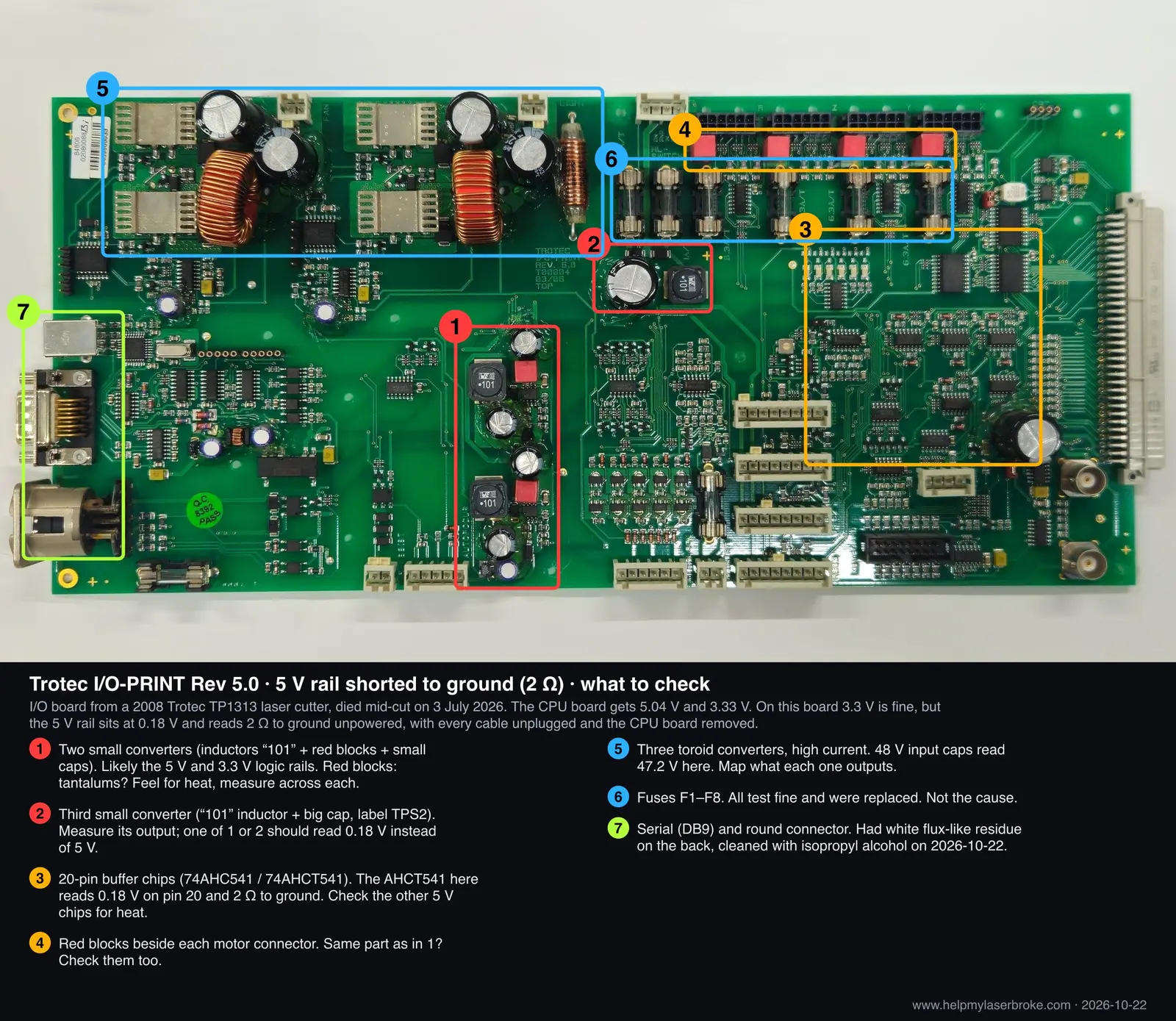
  • 5 V on the I/O board Supply pin of a 74AHCT541 reads 0.18 V. The 3.3 V chips next to it (74AHC541) read 3.3 V. Power off, the same pin to ground reads about 2 Ω: the 5 V rail is shorted. Still shorted with every cable unplugged except the 48 V input and the CPU board removed, so the short is on the I/O board. The 3.3 V chips read several hundred ohms to ground.
  • Keypad connector X22 (16 pins, machine on) No pin at 5 V, with the keypad ribbon on or off. One pin 3.33 V, three at 1.05 V, four at 0.48 V, the rest 0 V. Starting with the keypad unplugged changes nothing.

Is this normal?

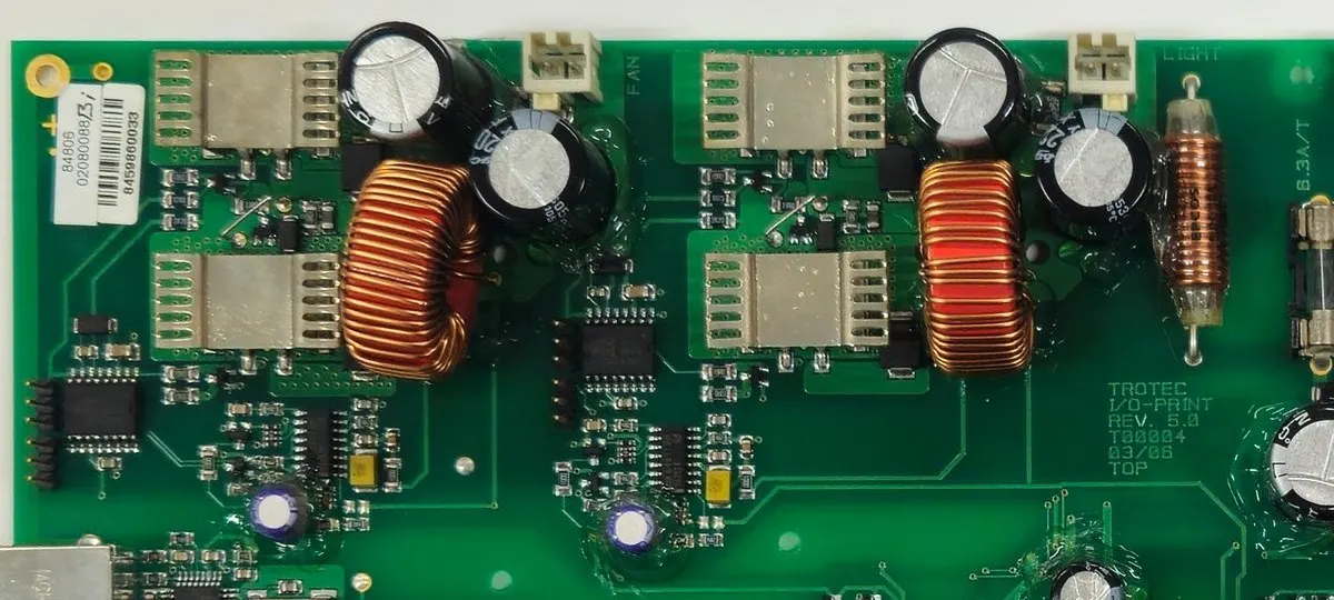
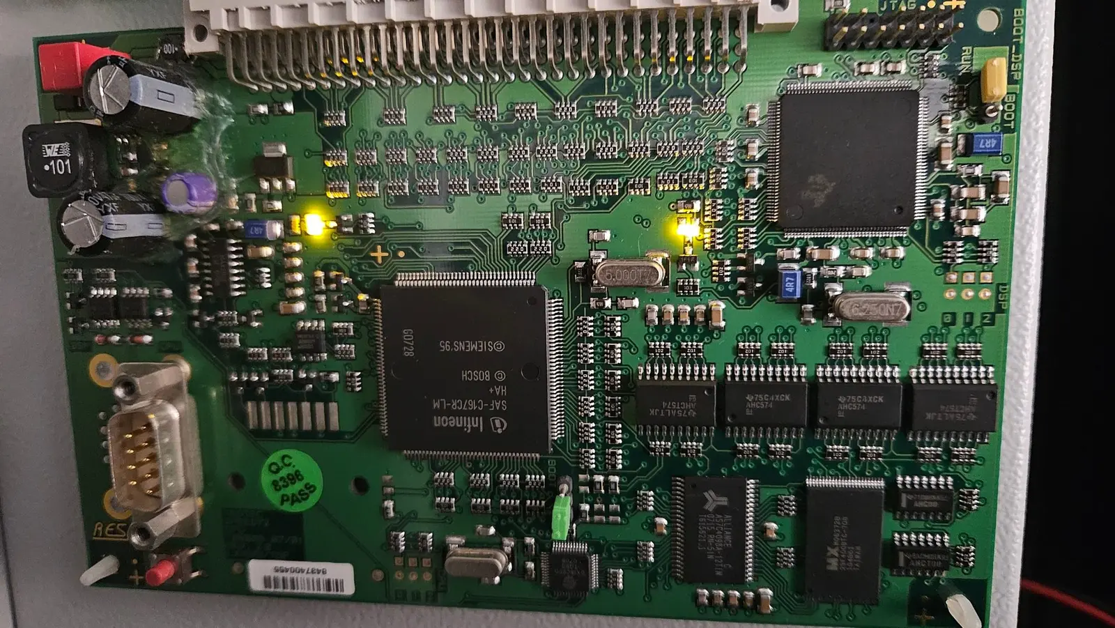
  • LEDs on the electronics boards Some are lit at power-on (see image below). Do they look ok?
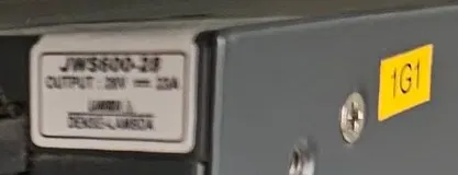
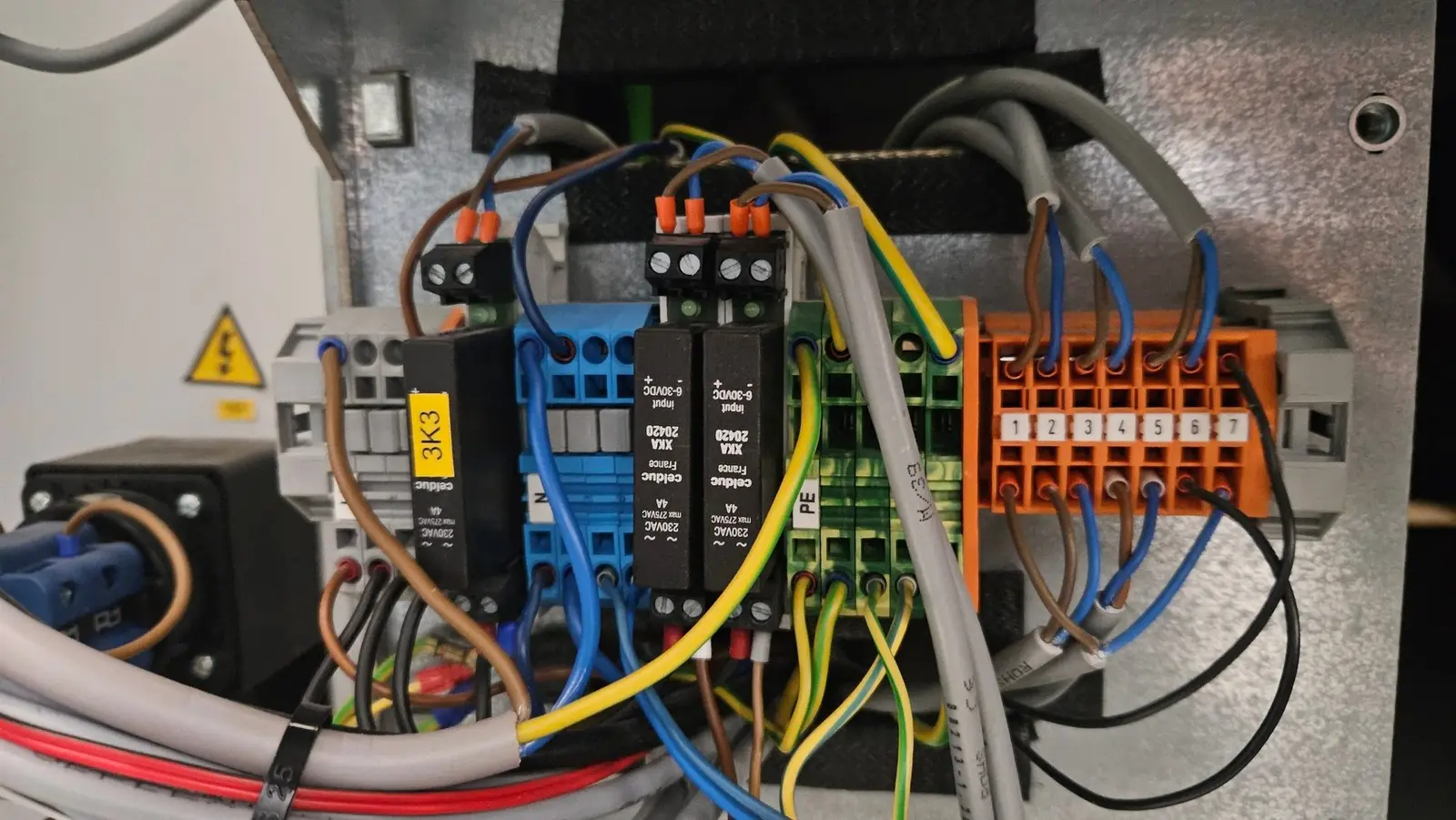
  • 1G1 + 1G2 · Lambda JWS600-28 outputs 32 V each with outputs disconnected (rated 28 V). Wired in series.

OK

  • Chiller / coolant flow 6 l/min, water circulating
  • Exhaust fan Runs
  • Board fuses All pass a continuity test. Replaced every one with a new fuse anyway: no change.
  • Interlock and emergency-stop loop Bridged X111 terminal 1 to 6 (bypasses the e-stop and all 8 door switches). No change at power-on.
  • 48 V at the I/O board 47.5 V on the X2/2–X2/3 wires, 47.2 V across the nearest large capacitor
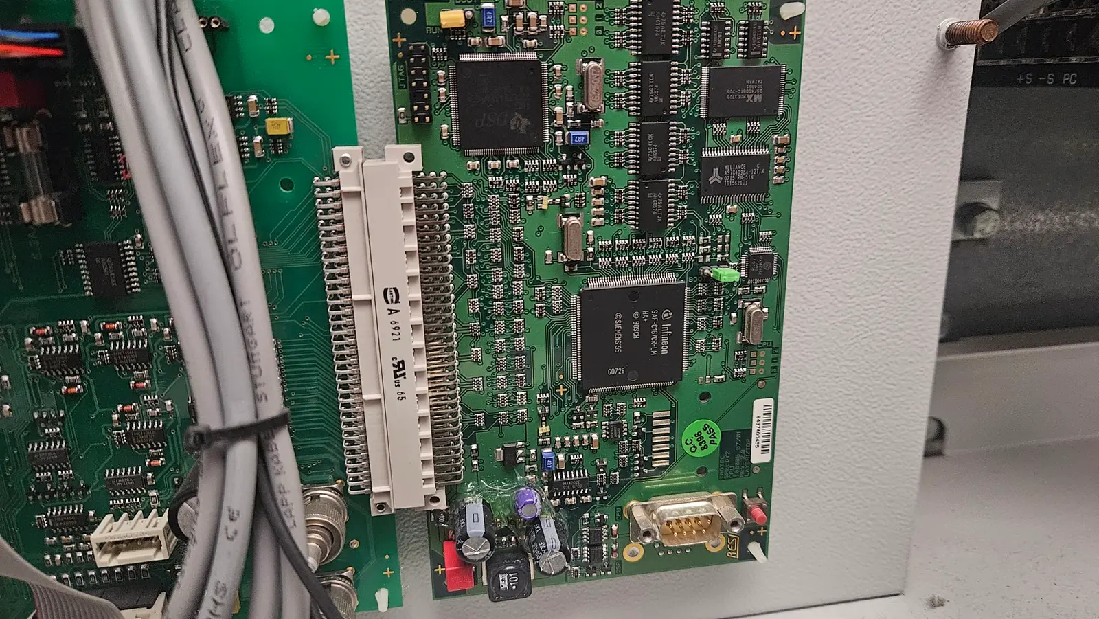
  • 5 V and 3.3 V on the CPU board 74AHCT574 supply pins 5.04 V, 74AHC574 supply pins 3.33 V
  • Visual inspection of the boards Nothing burnt, bulging or discoloured
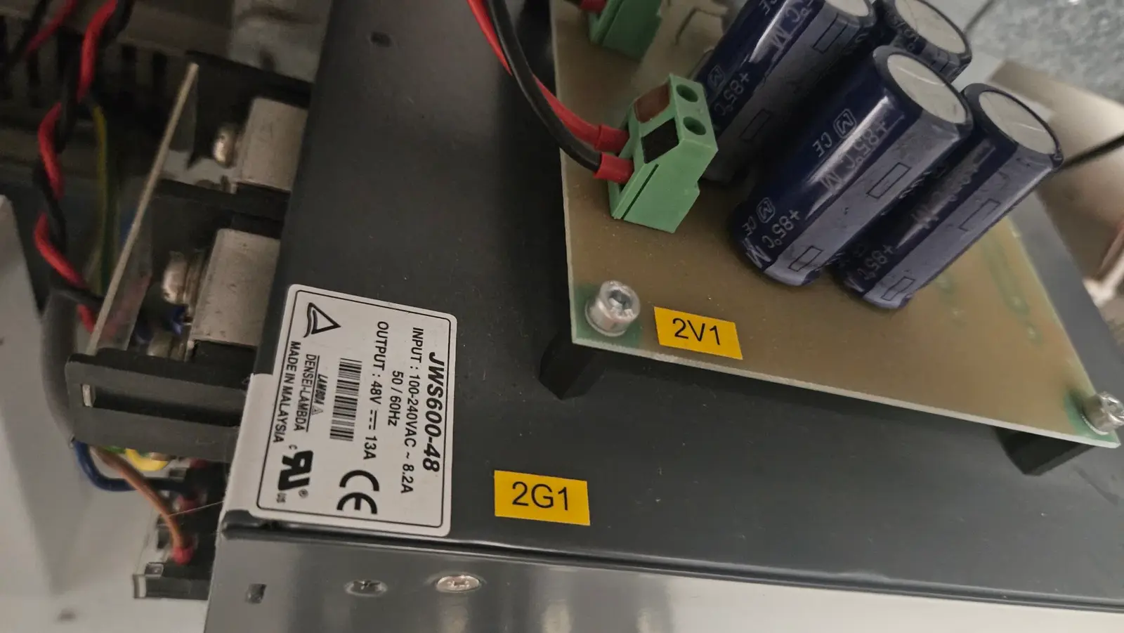
  • 2G1 · Lambda JWS600-48 output 48 V (rated 48 V)

Open questions

Quote the number when you reply, e.g. “Q3”.

  1. What does error −204 mean?

    It’s the last line in the JobControl log, logged the moment the machine died. The log is also full of −3 and −251 going back to 2024. Were those early warnings?

    1. 2026-07-02 19:45:27−3
    2. 2026-07-03 02:40:33−251
    3. 2026-07-03 02:40:37−3
    4. 2026-07-03 13:34:34−204
    Last 4 lines of TREX.LOG
  2. Why does it beep “ready” when nothing is ready?

    Two short beeps at power-on instead of one, then a dark keypad and no movement. After a while it beeps “ready” anyway. Opening and closing the cabin door also gets the “ready” beep a few seconds later. Does the controller just not know the panel and motors are dead?

    Close-up for Q2: Why does it beep “ready” when nothing is ready?
  3. Is 32 V normal for a 28 V Lambda JWS600-28?

    Both 1G1 and 1G2 read 32 V with their outputs disconnected. Normal with no load, or has the trim drifted? Both PSUs measure identical, so I'd be inclined to believe they are not at fault.

    Close-up for Q3: Is 32 V normal for a 28 V Lambda JWS600-28?
  4. What is shorting the 5 V rail on the I/O board?

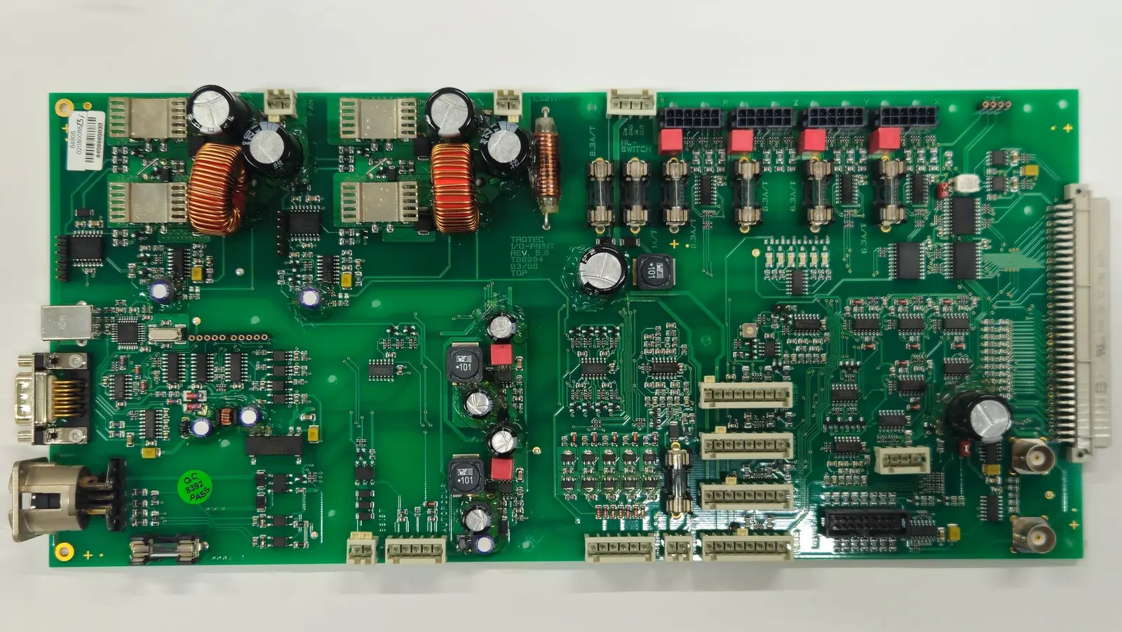
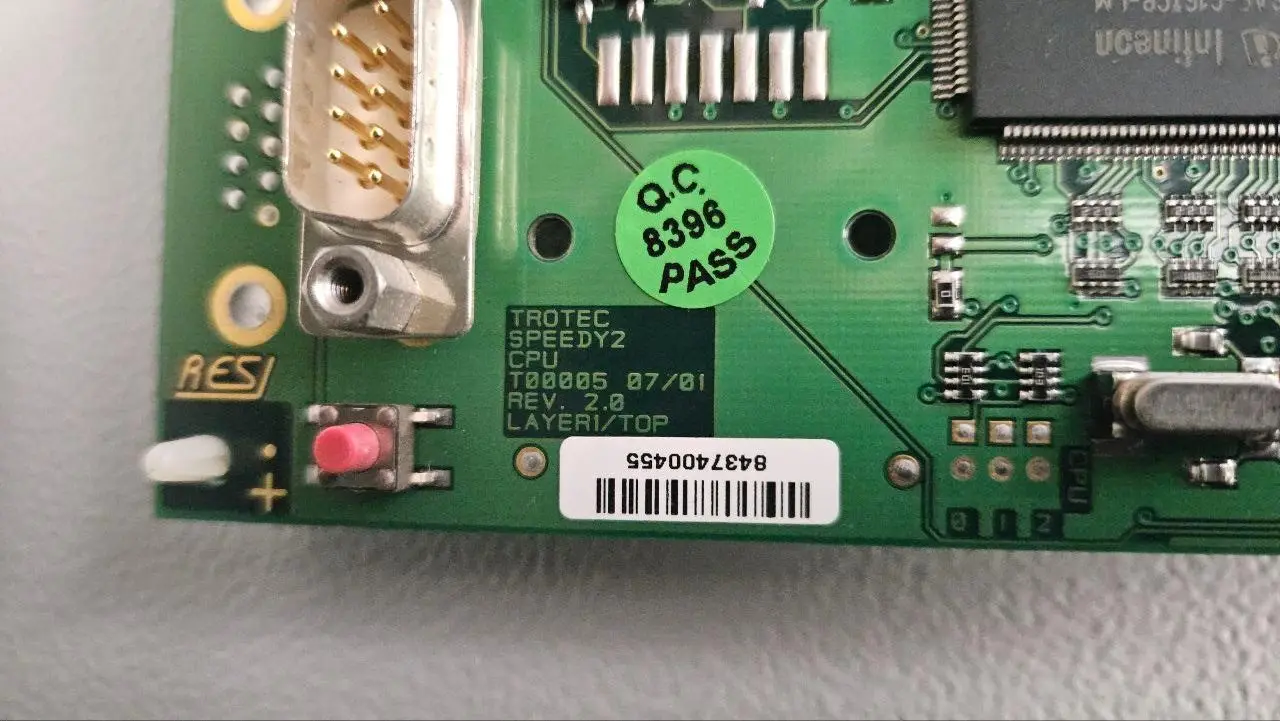
    The CPU board has 5.04 V and 3.33 V. On the I/O board the 3.3 V chips are fine but a 74AHCT541 gets only 0.18 V, and with power off its supply pin reads 2.2 Ω to ground. The keypad connector X22 has no 5 V on any pin. The short stays with every cable unplugged and the CPU board removed, so it is on the I/O board itself (Trotec I/O-PRINT Rev 5.0, T00004, 03/08). Which part is the likely culprit, and how do I find it with a multimeter?

    Close-up for Q4: What is shorting the 5 V rail on the I/O board?
  5. What should I measure next?

    I have a multimeter but I’m not an electronics engineer. Tell me the connector, the pins and the reading to expect, and I’ll post the result here. The wiring diagrams below have the connector numbers.

Wiring diagrams

From section 6.3 of the Trotec Professional operation manual. The sheets are drawn for the Professional 100W (2001), so my 2008 C60 may differ in places. Tap a sheet to enlarge.

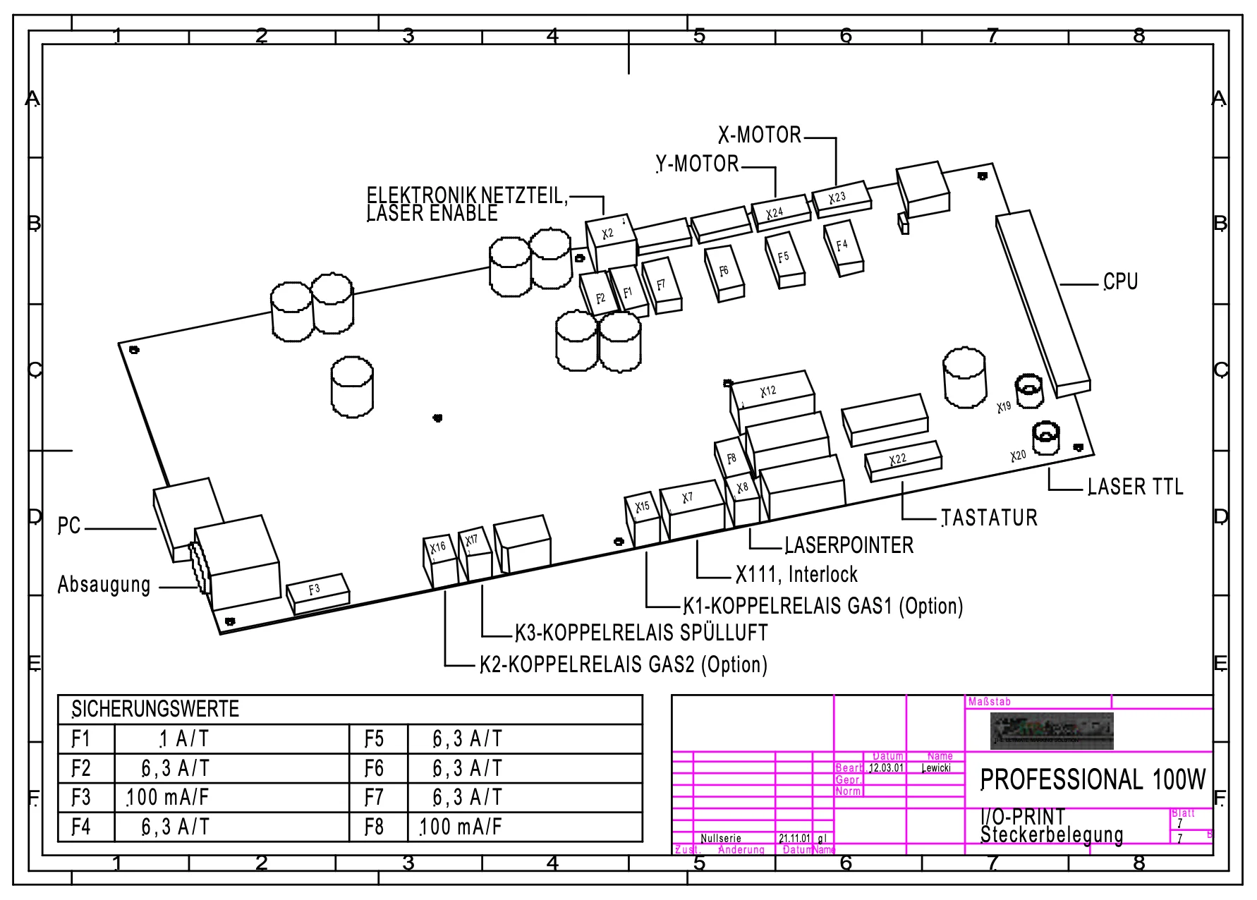
  • Wiring sheet 7: drawing of the I/O board with connectors X2, X7, X8, X12, X15–X17, X19–X20, X22–X24, the CPU slot, fuses F1–F8 and a fuse value table

    I/O board: connectors and fuses

    CPU, keypad (X22), X and Y motors (X23, X24), 48 V electronics supply and laser enable (X2), interlocks (X7/X111). Fuses: F1 1 A T · F2, F4–F7 6.3 A T · F3, F8 100 mA F.

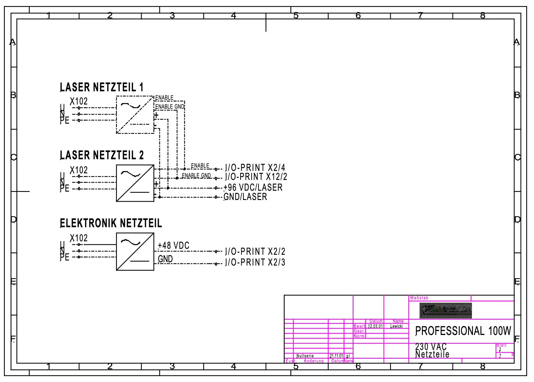
  • Wiring sheet 2: laser power supplies 1 and 2 and the electronics power supply, with outputs to I/O board X2/2, X2/3, X2/4 and X12/2

    Power supplies

    The electronics supply feeds +48 V to the I/O board at X2/2 (GND X2/3). The two laser supplies are enabled from X2/4 and X12/2.

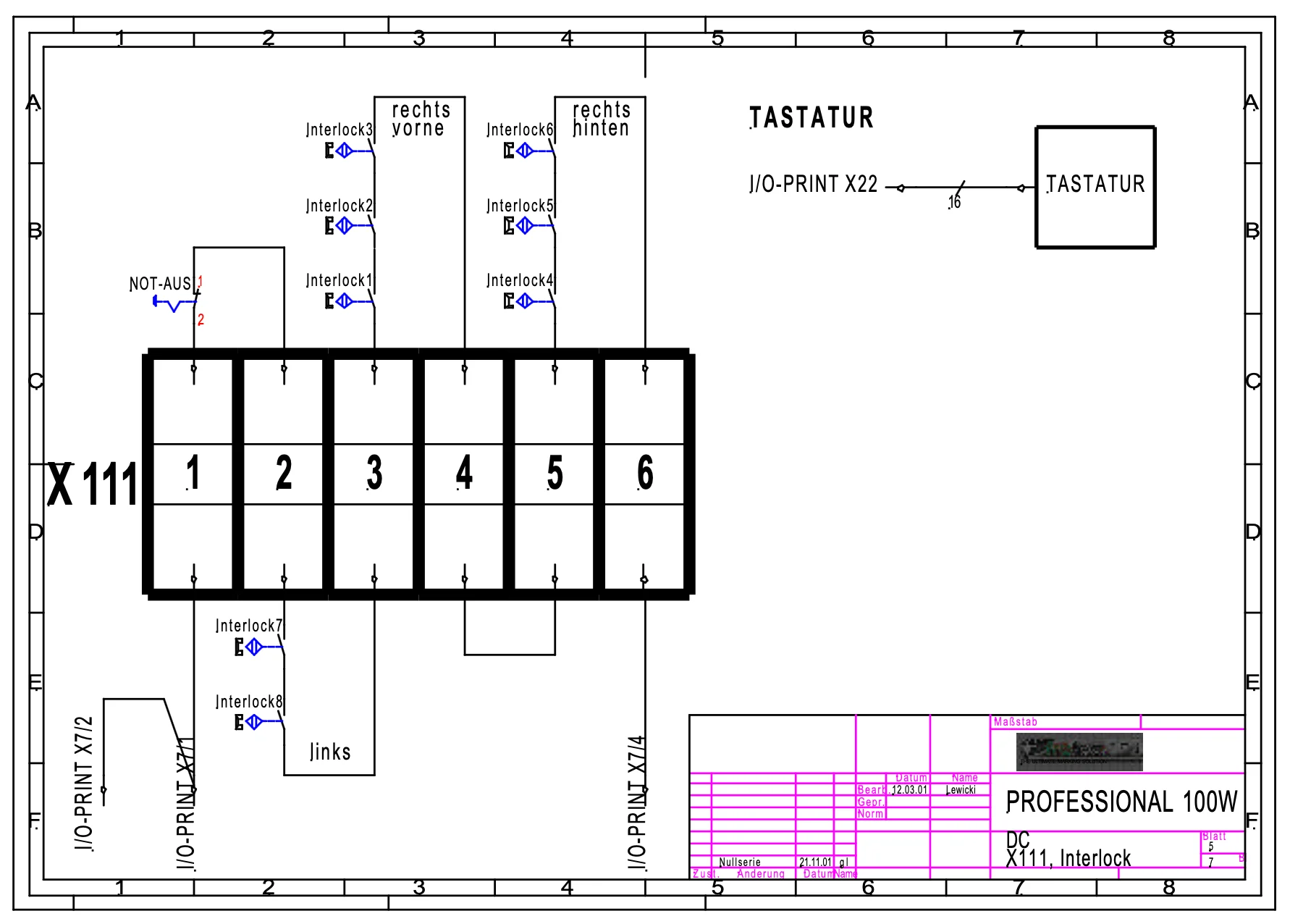
  • Wiring sheet 5: terminal block X111 with emergency stop and interlock switches 1 to 8, and the keypad connected to I/O board X22 with 16 wires

    Interlocks and keypad

    Emergency stop and door interlocks 1–8 run in series through X111 to X7/1, X7/2 and X7/4. The keypad connects to X22 with a 16-wire cable.

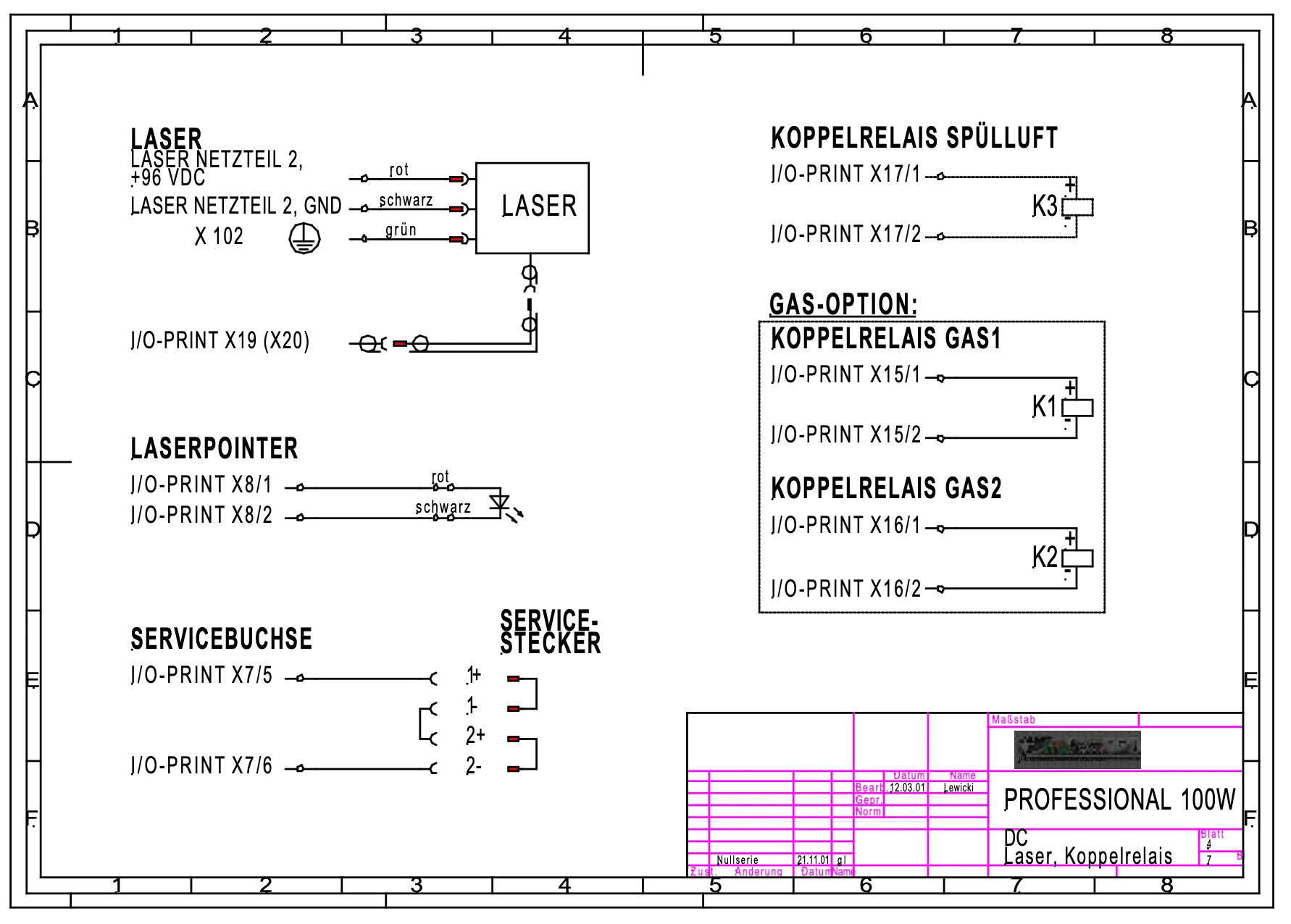
  • Wiring sheet 4: laser connections, laser pointer on X8, service socket on X7/5 and X7/6, and coupling relays K1 to K3 on X15 to X17

    Laser, pointer and relays

    Laser tube power and signal (X19/X20), red pointer on X8, air-assist relay K3 on X17, service plug on X7/5–6.

Full manual (PDF, 2.2 MB) German labels: Netzteil power supply · Tastatur keypad · Not-Aus emergency stop · Absaugung exhaust · Spülluft air assist

Photos

Machine details & logs

Model
Trotec TP1313, nameplate “Laser Professional C60”, SN PRO136
Built
March 2008, Wels, Austria. I bought it in 2022 at auction from Aalto University.
Support
Trotec ended support in 2017. Logimark, the Nordic reseller, declined to repair it.
Laser
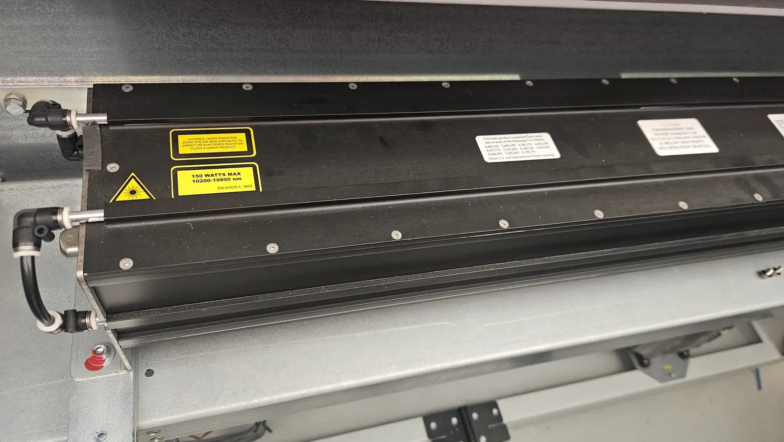
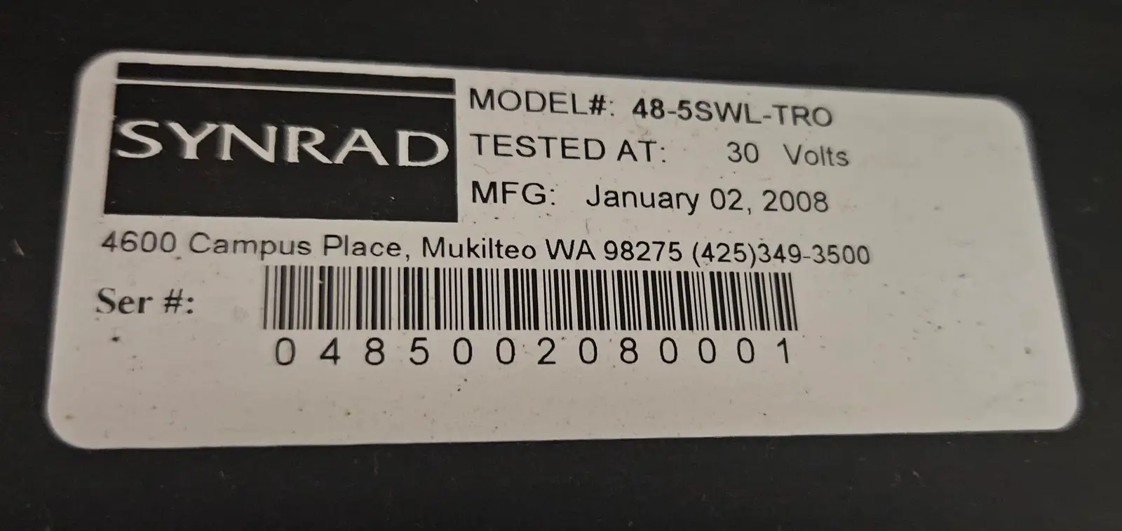
Synrad 48-5SWL-TRO CO₂, water cooled, 1300 × 1300 mm bed
Supplies
1G1 + 1G2 Lambda JWS600-28 (28 V) · 2G1 JWS600-48 (48 V) · 2V1 capacitor board
Mains
220–240 VAC, 16 A, 50 Hz
Firmware
CPU, Laser, DSP-X, DSP-Y all 1550
Software
JobControl 9.4.4.2 on Windows 7, USB-serial on COM4
Hours
Laser ≈ 1,883 h

Error codes in TREX.LOG since 2024

CodeCountFirstLast
−3442024-10-022026-07-03
−251222024-10-012026-07-03
13122024-12-272026-04-25
13812025-03-302025-03-30
14412026-06-302026-06-30
−20412026-07-032026-07-03

Downloads

How to help

Reply on Reddit

Theories, things to measure, “I had the same on my Speedy”. I’ll test it and post the result here, credited to you.

Open the thread

I’m also looking for

  • A technician in Finland or the Nordics (or anywhere!) who knows Trotec machines of this age
  • Spare boards from a 2008-era Trotec Professional or TP1313
  • The service manual or a JobControl error-code list
  • Any sort of software for troubleshooting the boards via a serial cable
Of course, I'm ready to compensate for your time! This machine means everything to me! 😥

Message me

Or email heikki@hexagon.fi

Updates

  1. The door makes it beep “ready”

    New clue. If I open the cabin door and close it again, a few seconds later the machine gives the same long “ready” beep it usually gives when it’s working normally. Panel still dark, head still not moving.

    So the controller sees the door switch and runs its “door closed, ready to go” routine. It does not seem to notice that the panel and the motors are dead. Added to the checks table and to the open questions.


  2. Found something: no 5 V on the I/O board

    The fuses all passed a continuity test in August, but to rule them out properly I swapped every one for a new fuse. Same relay click, same two beeps, dark keypad, no homing.

    Then I bridged the interlock loop at terminal block X111, pin 1 to pin 6, which bypasses the emergency stop and all eight door switches. No change.

    The 48 V supply arrives at the I/O board: 47.5 V on the X2 wires. Then I measured all 16 pins of the keypad connector X22 against ground with the machine on. No pin shows 5 V: one is at 3.33 V, three at 1.05 V, four at 0.48 V, the rest at 0 V. If the keypad is supposed to get 5 V from here, it isn’t. So I measured the supply pins of the logic chips directly. CPU board: the 74AHCT574s get 5.04 V and the 74AHC574s get 3.33 V, both rails fine. I/O board: the 74AHC541s get 3.3 V, but a 74AHCT541 gets 0.18 V. The 5 V rail on the I/O board is dead. That would explain a dark keypad and dead motors while the CPU happily boots and beeps. Power off, the same supply pin reads 2.2 Ω to ground. The rail is shorted. I unplugged every cable from the I/O board except the 48 V input and pulled the CPU board: still shorted. So the fault is a part on the I/O board. It’s on my bench now, photos in the gallery, including an annotated one with the parts I’m checking. The back had white crusty residue around the serial and round connector pins, probably old flux. I cleaned it off with isopropyl alcohol. Next: find the shorted part.

  3. The site is live

    Everything I know is now on this page: the symptoms, what I’ve measured, the full JobControl service snapshot, photos of the electronics and my narrated video.

    What I need most: someone who recognises error −204, or can tell me where to put the multimeter probes next. Reply in the Reddit thread or email me. I’ll post every result here, credited to you.

Follow via RSS